Tuesday, March 30, 2010
GAMBAR|FITUR NOKIA 6303i classic
Nokia 6303i classic
NOKIA 6303i classic
NOKIA 6303i classic REVIEW
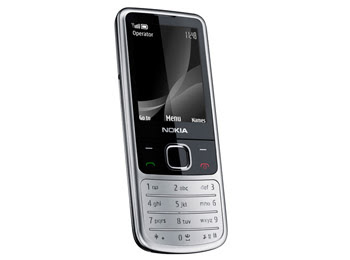
Nokia today announced the Nokia 6303i classic, a sophisticated and compact device that follows in the footprints of the Nokia 6303 classic and builds on the proven formula that made Nokia the world leader in mobile phones. The device is great value for money with its amazing feature list and an estimated retail price of EUR 105, before taxes and subsidies.

The 6303i classic now comes stomaching enhanced battery talents, enabling you to make up to 8 hours of calls. It’s also capable of letting you listen to around 30 hours of music via its built-in music player and FM radio, and will sit tight for over three weeks on standby.

Extending its rack of communication tools, the 6303i supports instant messaging for enhanced social savviness. It also features a 3.2-megapixel camera with dual LED flash, geared up for easily sharing your sharp snaps online.

We touched on the topic of refinement a few weeks ago and it’s place in mobile innovation and development cycle, and the 6303i classic is certainly another example of this to sit alongside the likes of the similarly honed E72. What do you think?

The 6303i classic begins shipping in selected territories this quarter.

The 6303i uses the S40 6th edition user interface. The interface is simple and intuitive. There is not much change in the UI over its predecessor 6303. The home screen has got slight make over, which features usual status reading like signal & battery status, caller ID. When the keypad is locked, if you press end key, it shows time and date. The menu system also got some renovation. The new mode displays a single icon at a time. The interface is boring as the icons lack the animations. Since it lacks multitasking, you can’t minimize java apps like Opera browser and do other tasks.

The Nokia 6303i Classic offers connectivity in the form of GPRS and EDGE, both of which are class 32. Micro-USB and blue tooth are also included as standard and offer additional connectivity options. The handset comes with an internal memory capacity of 55 MB, with a 2 GB card included in most packages, whilst for further memory capacity the existing microSD card slot and relevant cards can be used to increase capacity up to 16 GB.

The handset offers an impressive 2.2 inch TFT display screen which offers impressive levels of colour variance by virtue of its 16 million colour options. The handset offers the alternative of either ring or vibration alerts as well as the ability to utilise existing MP3 files as ringtones. The phone also comes with a speakerphone which provides effective hands free communication in addition to a 3.5 mm audio jack which offers the option of personal listening, should this be desired or required.

The Classic Nokia 6303i is an impressive handset, styled in a popular style with a range of functionality that makes it a viable option for many.

SPECIFICATIONS
General
2G Network GSM 900 / 1800 / 1900
Announced 2010, February
Status Available. Released 2010, March

Size
Dimensions 108.8 x 46.2 x 11.7 mm, 57 cc
Weight 96 g

Display
Type TFT, 16M colors
Size 240 x 320 pixels, 2.2 inches

Sound
Alert types Vibration, MP3 ringtones
Speakerphone Yes
- 3.5 mm audio jack

Memory
Phonebook 2000 entries, Photocall
Call records 20 dialed, 20 received, 20 missed calls
Internal 55 MB
Card slot microSD, up to 8GB, 2GB included, buy memory

Data
GPRS Class 32
EDGE Class 32
3G No
WLAN No
Bluetooth Yes, v2.1 with A2DP
Infrared port No
USB Yes, microUSB v2.0

Camera
Primary 3.15 MP, 2048x1536 pixels, autofocus, dual LED flash
Video Yes, QVGA@8fps; QCIF@15fps
Secondary No

Features
Messaging SMS, MMS, Email, IM
Browser WAP 2.0/xHTML, HTML
Radio Stereo FM radio with RDS
Games 8 + Downloadable
Colors Steel, Matt Black, Chestnut, Illuvial pink, White on Silver, Khaki on Gold
GPS No
Java Yes, MIDP 2.1
- Nokia Maps 2.0
- H.263/H.264 player
- MP3/WAV/eAAC+/WMA player
- Organizer
- Flash Lite 3.0
- Voice memo/dial
- T9

Friday, March 26, 2010

GAMBAR DAN FITUR Nokia 2330 Classic
NOKIA 2330 Classic
NOKIA 2330 ClassicNokia 2330 Classic REVIEW
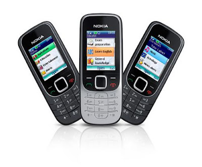
The Nokia 2330 Classic is an entry level Nokia phone with a classic design. With smooth rounded edges and a stylish flat keypad, the 2330 Classic features a VGA digital camera which can also capture video. Share your photos with friends using the 2330's built in Bluetooth or MMS and Email capabilities. The Nokia 2330 also features a built in FM radio so you can tune in to the latest hits and supports MP3 ringtones so you can choose your favourite track and set it as your ringtone.Presented to us in two colour choices, the Nokia 2330 classic will be available in black with the silver keypad trim, as pictured, or Deep Red. Weighing in at a polite 90 grams and with dimensions of 13.8mm x 46mm x 107mm, this handset fits neatly into most pockets. Offering a 1.8” TFT display with 65k colours and 160 x 128 pixels, the integrated VGA digital camera can be used with ease to create images and videos. These can be stored easily in the 32 Mbytes of memory. For those who like to listen to their favourite FM radio station whenever they can, the dedicated FM Radio key allows easy listening supported by the internal antenna. Once fully charged a talk time of 4.8 hrs and standby time of 540 hrs can be expected. Also offering all the usual suspects of SMS and MMS, Bluetooth® technology and a built in web browser, the user will be able to use the Nokia Xpress audio messaging service to share audio messages with compatible contacts. The Hands Free and Conference call features, audio recording and a good selection of ring tone formats also help to round off this elegant edition to the Nokia Classics range.

In summary, the Nokia 2330 Classic is an elegantly crafted handset which delivers all the minimum aspects we have come to expect in our mobile phones with the quality we have come to expect from Nokia. It is a lovely little phone, ideal for all ages, particularly those who don’t want to be blinded by science but want up to date basic applications. Calling, texting, gaming, web browsing, taking pictures, making videos and listening to music, all from a classy little handset

THE SPECIFICATIONS
General

Status Available
Introduced May 2009
Announced November 2008
Network (2G) GSM 900 / GSM 1800
Form factor Block
Antenna type Internal
SAR Value 0.980 W/Kg

Size
Weight 80.0 g (with battery)
Dimensions 107.0 x 46.0 x 13.0 mm

Display
Type Graphical
Coloured Yes, TFT, 65K colors
Size 1.80 inch
Resolution 128 x 160 pixels
- 5-way navigation key

Memory
Numbers in phone 1000
Received calls 20
Outgoing calls 20
Lost calls 20

Ringtones
Polyphonic ringtones Yes
Ringtone profiles Yes
- MP3

Networking
GPRS Yes
Bluetooth Yes
WAP Yes
Browser Yes, WAP 2.0/xHTML
Email client Yes

Features
Vibration Yes
SMS Send / Receive
MMS Send / Receive
Camera Builtin, VGA, 640x480 pixels
Java Yes, MIDP 2.0
Games Yes
Clock Yes
Alarm Yes
Calculator Yes
Calendar Yes
Voice memo Yes
T9 Yes
Handsfree Yes
FM Radio Yes

Thursday, March 25, 2010

GAMBAR DAN SPESIFIKASI Nokia 5630 XpressMusic
Nokia 5630 XpressMusic
Nokia 5630 XpressMusic REVIEW
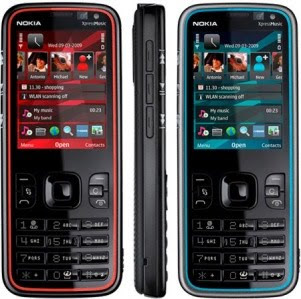
Nokia has first ensured that the new 5630 XpressMusic ticks the musical boxes. Comes with Music enabled in selected countries, it’s ready to soak up to 3,000 songs into its slender shell via a 4GB microSD memory card that comes in the box. Likewise, its tuneful talents extend to the ’say and play’ feature (first debuted on the 5320 XpressMusic last year), letting you speak the name of an artist of track to automatically play it. Plus, the Nokia 5630 comes loaded with a 3.5mm headphone connector, stereo Bluetooth, FM stereo and Internet radio to wrap up its music credentials. Now here comes the twist…

Alongside those core talents sit some unusual but welcome suspects on the features front. For starters it’s a full blown S60 device with fast HSDPA connectivity, meaning it’s primed to be loaded with apps and able to exploit many of the best Internet services out there, such as widgets (a la the 5800 and upcoming N97), Ovi Share and Nokia Messaging.

Similarly, it throws N-Gage gaming into the mix – only the second time Nokia’s premium gaming platform has been available on a non Nseries device (the 6210 just got there first). However, at just 12mm slim and weighing only 83g, this makes the Nokia 5630 XpressMusic the slimmest and lightest N-Gage gaming device to date.

Another smart addition is the home screen, which features a new Contacts Bar that has a definite widget feel to it – smartly animated, you can scroll through icons for up to 20 contacts and interact with them directly from the home screen.

The 5630 XpressMusic from Nokia comes with a complete N-Gage experience with an N-Gage shortcut on the homescreen. N-Gage offers an entire catalogue of mobile games from leading game publishers, a multiplayer game feature, and the ability to track progress, as well as add friends to play games against. In addition, the Nokia 5630 cell phone comes with a full focus 3.2 megapixel camera with flash function. Pictures or videos can be captured and shared via a favorite online community, such as Share on Ovi, Flickr, or Facebook.

SPECIFICATIONS
General

2G Network GSM 850 / 900 / 1800 / 1900
3G Network HSDPA 2100 / 900
Announced 2009, February
Status Available. Released 2009, June

Size
Dimensions 112 x 46 x 12 mm
Weight 83 g

Display
Type TFT, 16M colors
Size 240 x 320 pixels, 2.2 inches

Sound
Alert types Vibration; Downloadable polyphonic, MP3 ringtones
Speakerphone Yes
- 3.5 mm audio jack
- Dedicated music keys

Memory
Phonebook Practically unlimited entries and fields, Photocall
Call records Detailed, max 30 days
Internal 60 MB storage, 128 MB RAM
Card slot microSD, up to 16GB, 4GB included, buy memory

Data
GPRS Class 32
EDGE Class 32
3G HSDPA, 10.2 Mbps; HSUPA, 2 Mbps
WLAN Wi-Fi 802.11 b/g, UPnP technology
Bluetooth Yes, v2.0 with A2DP
Infrared port No
USB Yes, v2.0 microUSB

Camera
Primary 3.15 MP, 2048x1536 pixels, enhanced fixed focus, LED flash
Video Yes
Secondary VGA videocall camera

Features
OS Symbian OS, S60 rel. 3.2
CPU ARM 11 600 MHz processor
Messaging SMS, MMS, Email
Browser WAP 2.0/xHTML
Radio Stereo FM radio with RDS
Games Yes, N-gage + downloadable
Colors Red on black, Blue on grey, Chrome on grey
GPS No
Java Yes, MIDP 2.1
- WMV/RV/MP4/3GP video player
- MP3/WMA/WAV/RA/AAC/M4A music player
- Voice memo
- T9

Monday, March 22, 2010


Economic Optimization of Heat Sink Design
INTRODUCTION
This paper describes the analysis and derivation of an optimum heat
sink design for maximizing the thermoelectric cooling performance
of a laboratory liquid chiller. The methods employed consisted of
certain key changes in the design of the heat sink in order to improve
its thermal performance. Parametric studies were performed in order
to determine the optimized cooling system design per dollar."
"The objective of this project was to analyze the thermal performance
of an initial simple heat sink design and improve cooling
performance while reducing the cost and overall size of the cooling
system. Several changes were examined in an effort to improve the
thermal performance and/or to reduce overall cost. The result
obtained has provided some guidelines for the selection/design of the
most effective and economical heat sink configuration. These results
were somewhat surprising since they are contrary to what one might
instinctively expect without the benefit of the detailed analysis
presented in this paper.


Optimization of Heat Sink Design and Fan Selection in Portable Electronics Environment
Abstract
Modern portable electronics have seen component heat loads
increasing, while the space available for heat dissipation has
decreased, both factors working against the thermal designer.
This requires that the thermal management system be optimized
to attain the highest performance in the given space. While
adding fins to the heat sink increases surface area, it also
increases the pressure drop. This reduces the volumetric airflow,
which also reduces the heat transfer coefficient. There exists a
point at which the number of fins in a given area can be optimized
to obtain the highest performance for a given fan. The primary
goal of this paper is to find the optimization points for several
different fan-heat sink designs. The secondary goal is to find a
theoretical methodology that will accurately predict the
optimization point and the expected performance.


Saturday, March 20, 2010


HOW TO CALCULATE AND SELECT A HEAT SINK FOR A GIVEN SOLID STATE RELAY APPLICATION

The basic structure of a Solid State Relay includes an internal power semiconductor mounted to an electrical insulator which in turn is mounted to the Solid State Relay’s base plate. To form an assembly, the SSR with an accompanying thermal interface material placed on its base plate is then torque mounted to the Heat Sink.
The thermal model representing the above configuration includes the following elements:
A.
The selected SSR with specified thermal impedance (RΘ ssr), forward voltage drop (Vf), and maximum allowed internal operating temperature (Tj).
B.
The thermal interface material placed between the SSR and the Heat Sink and its specified thermal impedance (RΘ tp).
C.
The calculated minimum Heat Sink thermal impedance rating (RΘ hs) required for proper SSR operation.
D.
The operating environment’s max ambient air temperature in °C (TA ).


How to verify the proper Heat Sink
In certain instances, once the heat sink requirements for a SSR in a particular application have been determined and installed, it may be desirable to verify that the system does indeed provide adequate cooling to ensure reliable SSR operation.
The following is a relatively simple method to check this suitability, and essentially uses some of the calculations from SELECTING A SUITABLE HEAT SINK (above) in a reverse manner. This technique may also be used on existing systems in the field that might have been more or less “empirically” designed, to gain information on their performance and potential reliabilty. This method involves determining the temperature of the internal power devices

Thursday, March 18, 2010


Heat Sink Selection For Solid State Relay Applications
ABSTRACT
Heat Sinks are required to insure the proper operation and long term reliability of Solid State Relays because they provide a means to dissipate the power that is normally developed by the SSR into the surrounding ambient air and maintain a safe operating temperature. Selecting the correct Heat Sink for any given SSR application involves coordinating form factor, size, mounting and thermal impedance rating. This paper discusses “Why Heat Sinks are Required for Reliable Solid State Relay Operation”, how the minimum required Heat Sink thermal impedance rating is calculated based upon application operating conditions, and includes an example calculation.


Selecting a Suitable Electronic Circuit Heatsink
Due to the forward voltage drop of the output SCRs, solid state relays generate an internal power loss. The amount of power generated is afunction of the load current. The manufacturer provides power loss curves, as shown in Fig 1. At normal load currents the power loss can be estimated at 1 Watt for every 1 Arms of load current. In order to maintain an acceptable power switch junction temperature, some form of
heatsink must dissipate the heat generated by the power loss. For most printed circuit board types, the relay current rating is established by measuring the thermal impedance, from the dissipating elements to air, using the relay package as the heat sink. Some printed circuit board types are available with an integral heatsink; their ratings reflect the additional effects of the integral heatsink.

Tuesday, March 16, 2010

GAMBAR DAN SPESIFIKASI NOKIA C5


Engadget queried the NOKIA C5’s smartphone credentials, which in turn poses an interesting question in terms of what expectations are now placed on a device to be dubbed a smartphone? The Nokia C5 is built on the S60 3rd edition platform of Nseries fame, and comes with a host of IM and social networking features built in. It also comes loaded with free walk and drive voice-guided navigation courtesy of Ovi Maps. Not to mention speedy HSDPA connectivity, granting maximum speeds of up to 10.2 Mbps via your operator, and HSUPA for rapid uploads of up to 2Mbps over the air. Does a smartphone need a large touchscreen and heaps of onboard memory to be called a smartphone? Let us know what you think below. However, Engadget did also highlight what good value it thinks the C5 presents:

NOKIA C5 SPECIFICATIONS

Brand / Type
Brand Nokia
Type C5
Form factor Candybar
Color Black, White
Network
Phone Network EDGE, GPRS, GSM, HSDPA (3G), HSUPA
Service 850, 900, 1800, 1900, 2100
Connectivity
Bluetooth v2.1 with A2DP
Infrared No
Wi-Fi (WLAN) No
USB MicroUSB v2.0
Fax / Data Yes
Display
Main display Color TFT
Color display 16.000.000 colors
Dimensions 2.2 in.
Resolution 240 x 320 pixels
External display No
Memory
Internal memory 50MB
External memory 16GB
Memory slots Yes
Storage types MicroSD, MicroSDHC
Basic
Battery Standard battery, Li-Ion 860 mAh (BL-5CT)
Standby time 670 hours
Talk time 12 hours
Calling
Vibrate alert Yes
Photo ID Yes
Ringtones MP3
Camera
Camera Yes
Megapixels 3.15 megapixels
Maximum photo resolution 2048x1536 pixels
Digital zoom Yesx
Optical zoom No
Auto focus Yes
Flash Yes
Recording video Yes
Second (front) camera Yes
Messaging
SMS Yes
MMS Yes
T9 text function Yes
E-mail Yes
Internet browsing Yes
Entertainment
FM radio Yes
Java Yes
Audio player eAAC, MP3, WAV
Video player H263, H264, MP4, WMV
Features
Add ringtones Yes
Organiser Document viewer (Word, Excel, PowerPoint, PDF), Organiser, Voice memo
Video call Yes
Other features Symbian OS 9.3, 2GB included, S60 rel. 3.2, Speakerphone, 3.5 mm audio jack, Downloadable games, GPS with A-GPS support, Nokia Maps
Format
Weight 3.2 oz.
Dimensions (H x W x D) 4.4x1.8x0.5 in.


Thermal Equation Parameters
Many parameters contribute to a design's thermal circuit, including the
device's maximum power consumption for the design, the maximum
environment temperature, package characteristics, and airflow at the
device.

Maximum Power Consumption (P)
Use the power calculator values from design simulations in the Altera
Quartus® II software (or the device's power calculator at
http://www.altera.com) to estimate the maximum power consumption
of the device. Once a prototype design is available, measure the actual
power consumption and use this value for thermal calculations.
Maximum Temperature (TJ & TA)

The maximum ambient and junction temperatures are found in the data
sheet for the device under Device Absolute Maximum Rating and the
operating junction temperature is found under Device Recommended
Operating Conditions. The temperature must be kept within the
maximum conditions or damage could occur. The junction temperature
should be kept within the recommended operating conditions to ensure
the device achieves the performance reported by the Quartus II software.

HEAT TRANSFER Basic Theory
The rate at which heat is conducted
through a material is proportional
to the area normal to the heat flow
and to the temperature gradient
along the heat flow path. For a one
dimensional, steady state heat flow
the rate is expressed by Fourier’s
equation:


Sunday, March 14, 2010


HEATSINK BASICS
All semiconductor devices have some electrical resistance, just
like resistors and coils, etc. This means that when power
diodes, power transistors and power MOSFETs are switching
or otherwise controlling reasonable currents, they dissipate
power — as heat energy. If the device is not to be damaged by
this, the heat must be removed from inside the device
(usually the collector-base junction for a bipolar transistor, or
the drain-source channel in a MOSFET) at a fast enough rate
to prevent excessive temperature rise. The most common way
to do this is by using a heatsink.

To understand how heatsinks work, think of heat energy itself
as behaving very much like an electrical current, and
temperature rise as the thermal equivalent of voltage drop. We
also have to introduce a property of materials and objects
known as thermal resistance, which behaves in a very similar
way to electrical resistance: the more heat energy ‘flowing’
through it, the higher the temperature rise across it. As you
might imagine metals like copper and aluminium have very low
thermal resistance, while air tends to have a relatively high
resistance. So do many plastics and ceramic materials.


HEAT TRANSFER FUNDAMENTALS
Introduction
The objective of thermal management programs in electronic packaging is the efficient removal of heat from the semiconductor junction to the ambient environment. This process can be separated into three major phases:

1) heat transfer within the semiconductor component package;
2) heat transfer from the package to a heat dissipater (the initial heat sink);
3) heat transfer from the heat dissipater to the ambient environment (the ultimate heat sink)


Heatsink 

Friday, March 12, 2010


The Effects of Heat on Electronic Circuits and Devices
Charles Nogales, VP of Engineering at Emulex, talks about the effects of heat on electronic circuits and devices, such as HBAs, and how heatsinks play a role in keeping networking and server product


Thermal Management Using Heat Sinks
Thermal management is an important design consideration with complex
devices running at high speeds and power levels as these devices can
generate significant heat. Proper thermal management can increase
product performance and life expectancy. The thermal management
requirements for a programmable device depend on its application.
AlteraR packages are designed to minimize thermal resistance
characteristics and maximize heat dissipation. However, in some cases,
complex designs require heat dissipation greater than packages provide.
This application note discusses ways to dissipate heat, how to calculate
the heat dissipation of a device, and how to determine if a device requires
a heat sink in an application.


Tuesday, March 2, 2010

Based amplifier IC's offer many advantages including high efficiency, high gain, low standby current, low component count, small size and, of course, low cost. It is little wonder that audio amp IC's have replaced most discrete transistors in consumer electronic devices. While many experimenters have stayed away from these little black Mysteries, I am going to uncover some of their secrets and demonstrate how easy they are to use


Rangkaian Amplifier IC LM380

Amplifier IC LM380 comes in two flavors; LM380 and LM380-8 with output powers of 700 milli-watts and 2 watts respectively. A schematic drawing below depicts the 8th and LM380-LM380.

Rangkaian Amplifier IC LM380-8Skema Rangkaian Amplifier IC LM380-8

Rangkaian Amplifier IC LM380Skema Rangkaian Amplifier IC LM380

The LM380-8 comes in an 8-pin package and its basic circuit is virtually identical to the LM380 except for the different pin out. The LM380 comes in a 14-pin package and pins 3,4,5,10,11 and 13 are connected to ground to act as a heat sink. Experience has shown the LM380 should be soldered directly to the circuit board (no IC socket) if it is going to be operated at its full rated output of 2 watts. This IC can become quite warm and it's important to get rid of excess heat through the pins. The primary advantages of the LM380 series IC's are higher output power, very low distortion and low external parts count.

Rangkaian Amplifier V-Mosfet 100 Watt

Another design that uses the output transistor technology V-MOSFET. The transistors are we offer many advantages over a simple bipolar transistor, such as high speed, thermal stability, low distortion, etc.

Rangkaian Amplifier V-Mosfet 100 WattSkema Rangkaian Amplifier V-Mosfet 100 Watt

The use of diodes D2 until D5 in combination with the resistances R17-19, they protect the gates of transistors v-fet from exceeds the voltage ± 14V and it creates perforation in very thin layer SiO2, that is used as insulation in the gate. This way of protection is common in all the amplifiers that use these transistors. The total gain of amplifier is 32.6, regulated from the R18, R6 and R8, in the negative feedback. Also is used enough the use of local feedback for stabilisation of operation under all the conditions. Because the transistors v-fet have positive factor of temperature, with result with the increase of temperature is increased also their resistance. This increase has as result the reduction of current that via the transistor, hence also his power. The use of separated supply in the stages of drive and exit, ensures stability and reject of distortion of intermodulation.

Series of VMOS FET POWER [ 2SK134 or 2SK135 ] [ 2SJ49 or 2SJ50 ], they are that, more above transistor they are not produced more by the Toshiba and are enough difficult they are found henceforth. They can be replaced with [ 2SK1530 in the place of 2SK135 ] and [ 2SJ201 in the place of 2SJ50 ]. The new transistors are in plastic case ΤΟ-3Ρ and no TO-3, bear in bigger supply of operation and have positive factor of temperature. This mean that with the increase of temperature, is increased and the current that is gone through from through the transistor. The new transistors him I have still not tryed and me it would interest to learn if somebody him used also with which results.

List Componet

R1=27Kohm
R2-11=4.7Kohm
R3-4=5.6Kohm
R5=47Kohm
R6=1Kohm
R7-10-21=22Kohm
R8=12ohm
R9=1Mohm
R12=33ohm
R13-20=82ohm
R14=33ohm
R15=2.7Kohm
R16=270ohm
R17-19=680ohm
R18=33Kohm
R22-23=0.33ohm 5W
R24=8.2ohm
R25=10ohm 1W
TR1=470ohm trimmer
TR2=4.7Kohm trimmer

C1=1uF 63V mkt
C2=1nF 100V*
C3=100uF 16V
C4=100nF 100V*
C5-7=22uF 16V
C6=4.7pF ceramic
C8=47uF 16V
C9=1nF 100V*
C10-11=100uF 100V
C12-14=100nF 250V mkt
C13=150nF 100V mkt
C15=100uF 35V

D1=12V 0.5W Zener
D2.....5=8.2V 1W Zener
L1=20 turns 0.6mm on R25

Q1-2=BC 547
Q3=2N5460 fet
Q4-5=MPSA93
Q6-8-11=BC182
Q7-10=MPSA43
Q9=BC212
Q12=2SK134 or 2SK135
Q13=2SJ49 or 2SJ50


blogger templates | Make Money Online