Wednesday, April 1, 2009
Transistor Schmitt Trigger Oscillator
The Schmitt Trigger oscillator below employs 3 transistors, 6
resistors and a capacitor to generate a square waveform.
Pulse waveforms can be generated with an additional diode
and resistor (R6). Q1 and Q2 are connected with a common
emitter resistor (R1) so that the conduction of one transistor
causes the other to turn off. Q3 is controlled by Q2 and
provides the squarewave output from the collector.
X'tal Oscillator Frequency
This circuit may used as clock frequency for many digital
circuits. I got this circuit from a microcontroller clock generator

555 Pulse Generator
A 555 pulse generator circuit with a difference, the initial
pulse is tailored by additional circuitry to match the duration
of subsequent pulses.
of this circuit is the 741, a general-purpose operational amplifier.
This circuit employs a single power supply Vs that can range
from +5V to +15V.

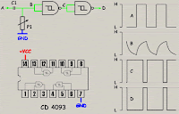
Changing the pulse width
The previous assembly gives a rectangular signal with a duty
cyclic equal to 50 %. We can need to change it to produce
pulses for example. A simple means is to use a variable RC
circuit and to reshape the signal obtained by means of a
Schmidt trigger , here a CD 4093 which allows to use a wide
range of voltage.
Labels: Signal Generator Circuit
0 Comments:
Subscribe to:
Post Comments (Atom)

