Monday, April 6, 2009
Constant Current Battery Charger
Simple Power Supply and Charger Circuits
Figure 4 shows a simple power supply circuit. I have tested with KABO,
it works fine. For those who have a big capacity rechargeable battery,
the resistance value of R can be selected for approx. 10% output
charging current. DC in can be higher if your battery voltage higher than
8.4V, say. To ensure the output current is within the value calculated by
R, measure DC current before. The maximum supply for LM317 is ~35V.
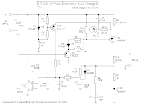
A Simple Peak-detecting Nicad Charger
The circuit consists of two parts, a constant current generator using
a PNP power transistor (Q2), and a peak-detecting shutoff circuit
using a high-gain opamp (IC1). To start the charge cycle, switch
SW1 is momentarily closed, causing C1 to discharge. As IC1's
inverting input is now higher than its non-inverting input, its output
goes low, turning on Q1. This lights the red "charge" LED (D2) and
provides about 80mA through R6 and R7 to turn on Q2, which starts
charging the battery. Charge current flows through R8 on its way to
the battery. When the voltage across R8 exceeds about 0.6V, Q3
starts to turn on and robs current from the base of Q2. This regulates
the output current to an amount determined by the value of R8.
Labels: Battery Charger, current
0 Comments:
Subscribe to:
Post Comments (Atom)
